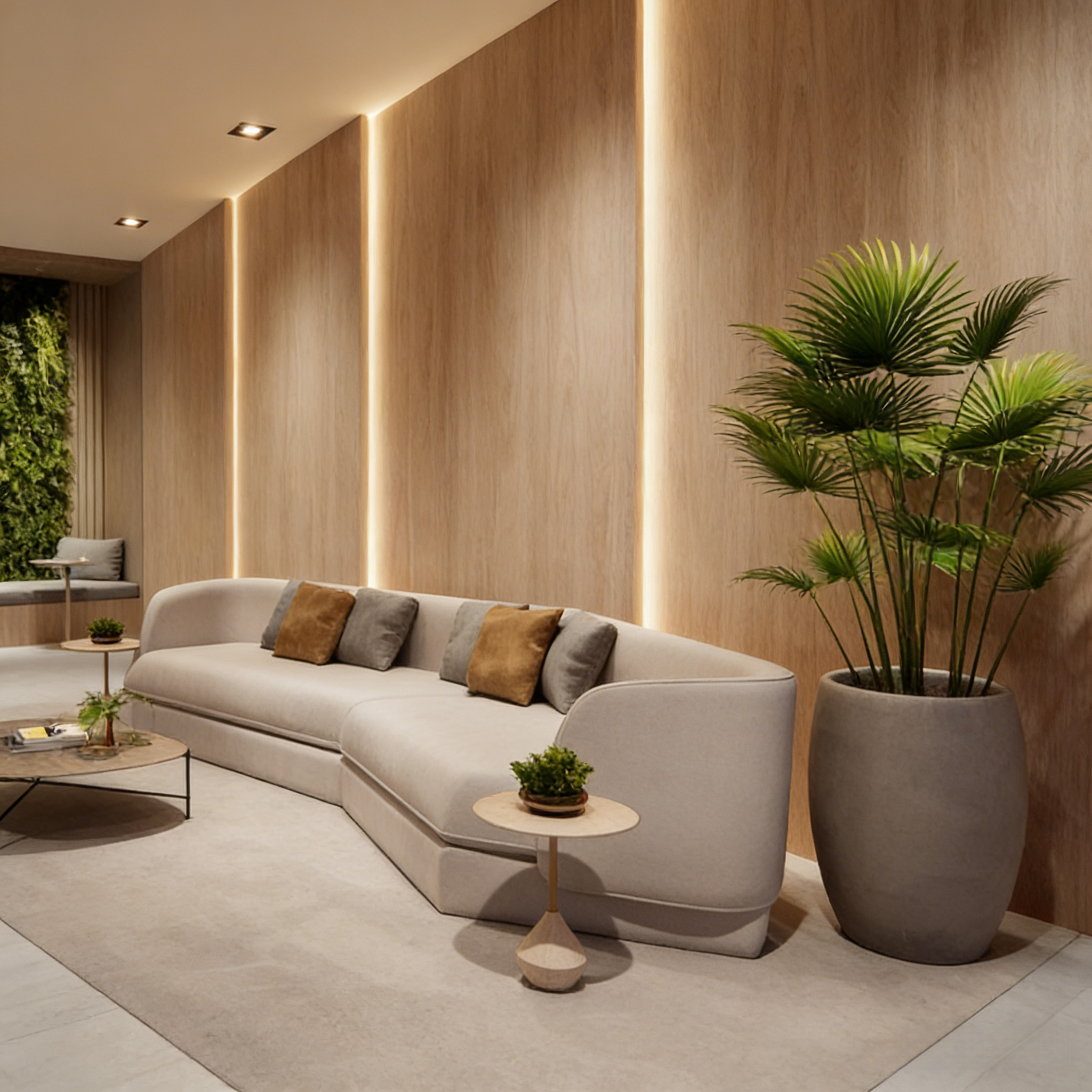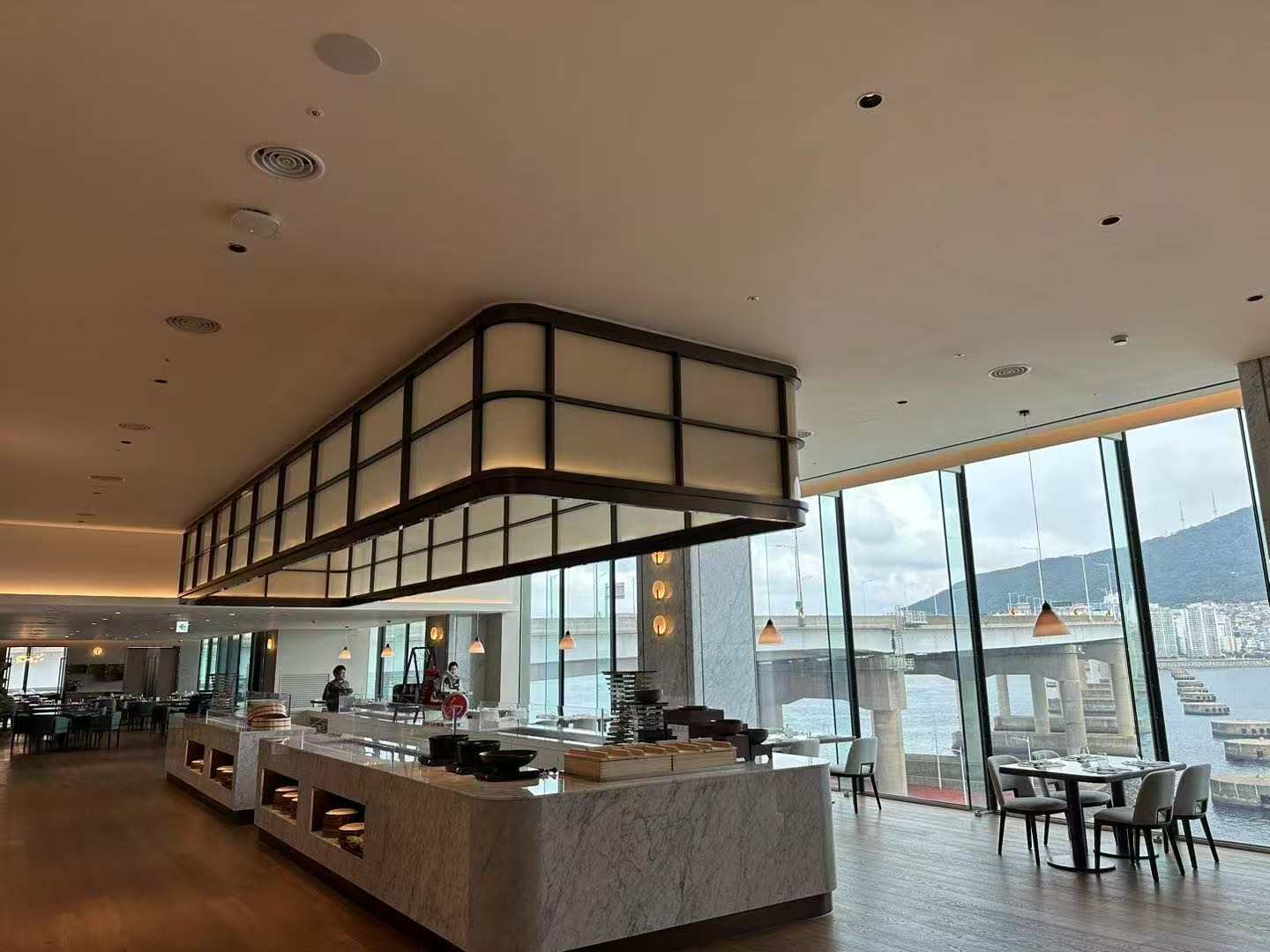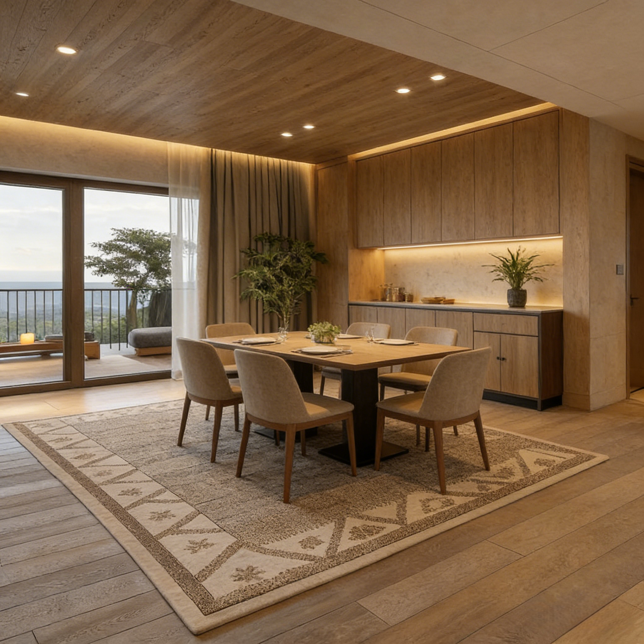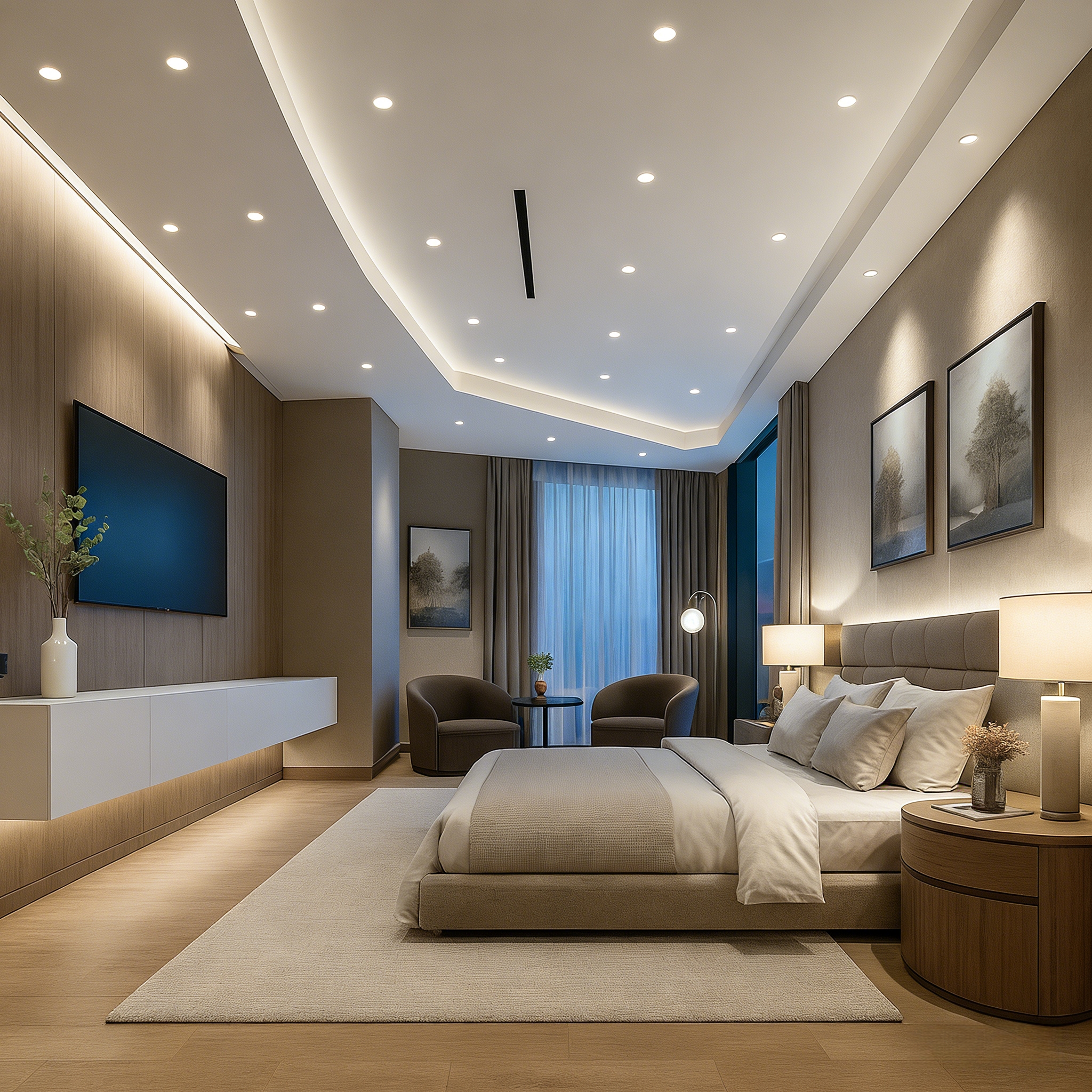
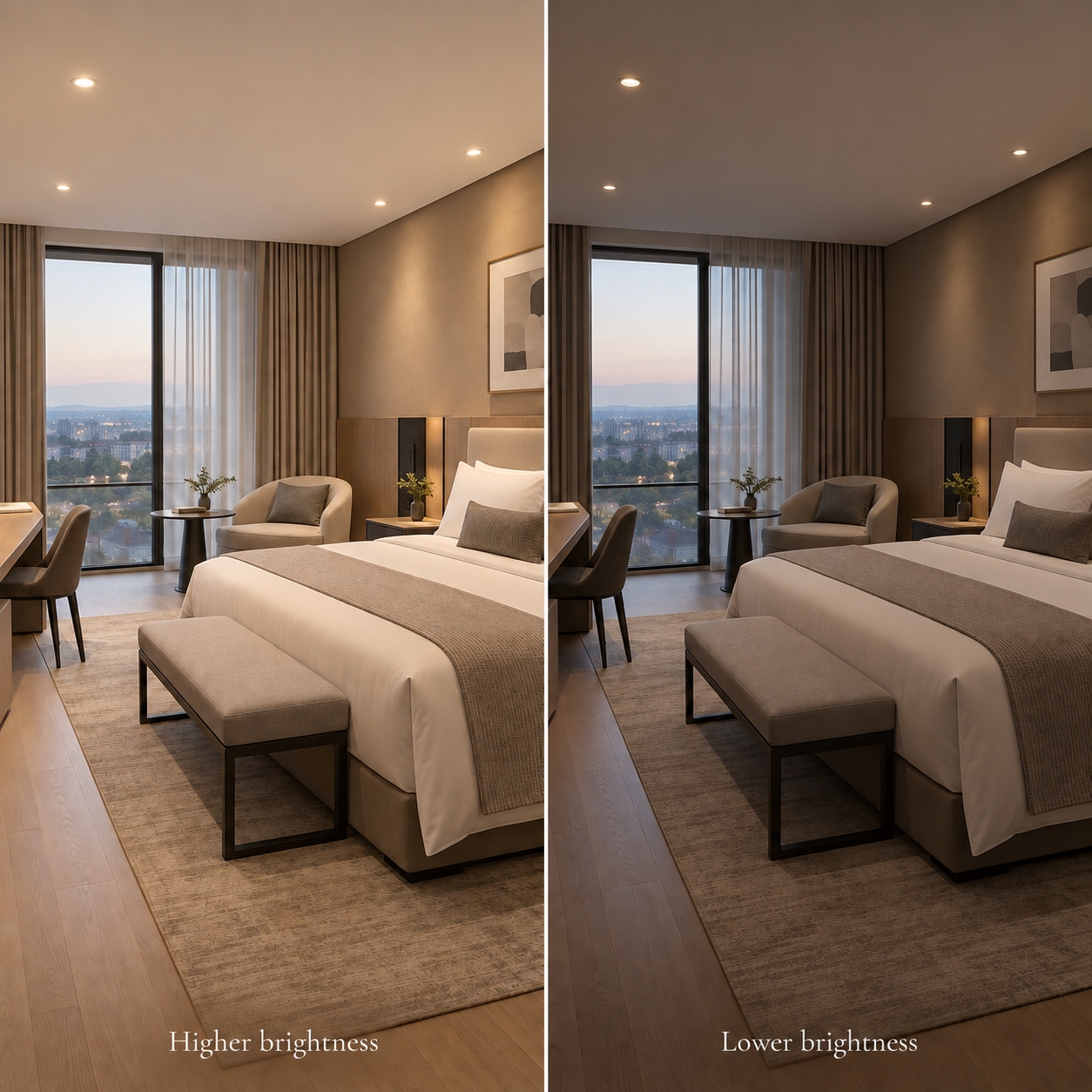
Dimming can make a guest room more comfortable, adapt an office to daylight or change a restaurant’s atmosphere through the evening. But a downlight labelled “dimmable” will work properly only when its LED driver and control system are compatible.
Leading-edge, trailing-edge, 0–10V and DALI describe different ways to send a dimming command. They differ in wiring, control features and commissioning requirements. This guide explains how each works and what to check before specifying LED downlights.
| Method | How it controls the driver | Typical planning consideration |
|---|---|---|
| Leading-edge | Cuts the beginning of each AC waveform cycle | Confirm the driver and dimmer are approved to work together |
| Trailing-edge | Cuts the end of each AC waveform cycle | Check compatibility, load range and low-level performance |
| 0–10V | Sends an analogue signal over control wires | Confirm wiring, source/sink compatibility and off behaviour |
| DALI | Sends digital commands over a control bus | Plan compatible devices, addressing, scenes and commissioning |
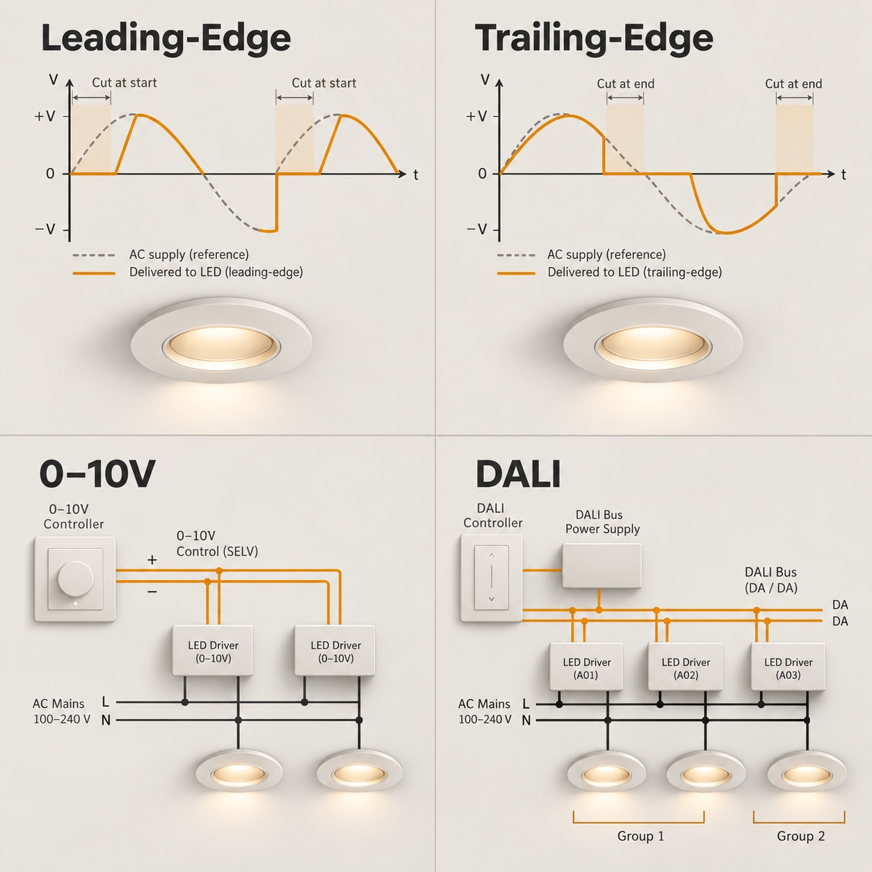
Leading-edge dimming is a type of phase-cut dimming. The dimmer delays the start of each AC waveform cycle delivered to the driver. It is also called forward-phase dimming.
It may be encountered in existing installations, making it relevant to renovation projects. However, the presence of a leading-edge wall dimmer does not establish that a new LED downlight will dim well with it. The driver must support the control method, and the combination should be tested for its usable dimming range, flicker, noise and reliable switching.
Trailing-edge dimming, also called reverse-phase dimming, cuts the end of each AC waveform cycle. It is often used with LED loads, but compatibility still depends on the specific driver and dimmer.
Do not assume that every driver described as “Triac dimmable” supports both leading-edge and trailing-edge controls. Request the manufacturer’s stated dimmer type or compatibility list. Also check the minimum and maximum load permitted on each dimming circuit.
Phase-cut control can be practical for a room or small group of fixtures, particularly where the project is retaining an existing mains-wiring arrangement. It offers a relatively straightforward user experience, but performance is highly dependent on the exact pairing of dimmer, driver and load. Guidance on successful LED phase-cut dimming recommends checking both the luminaire and dimmer documentation for tested combinations and circuit limits.
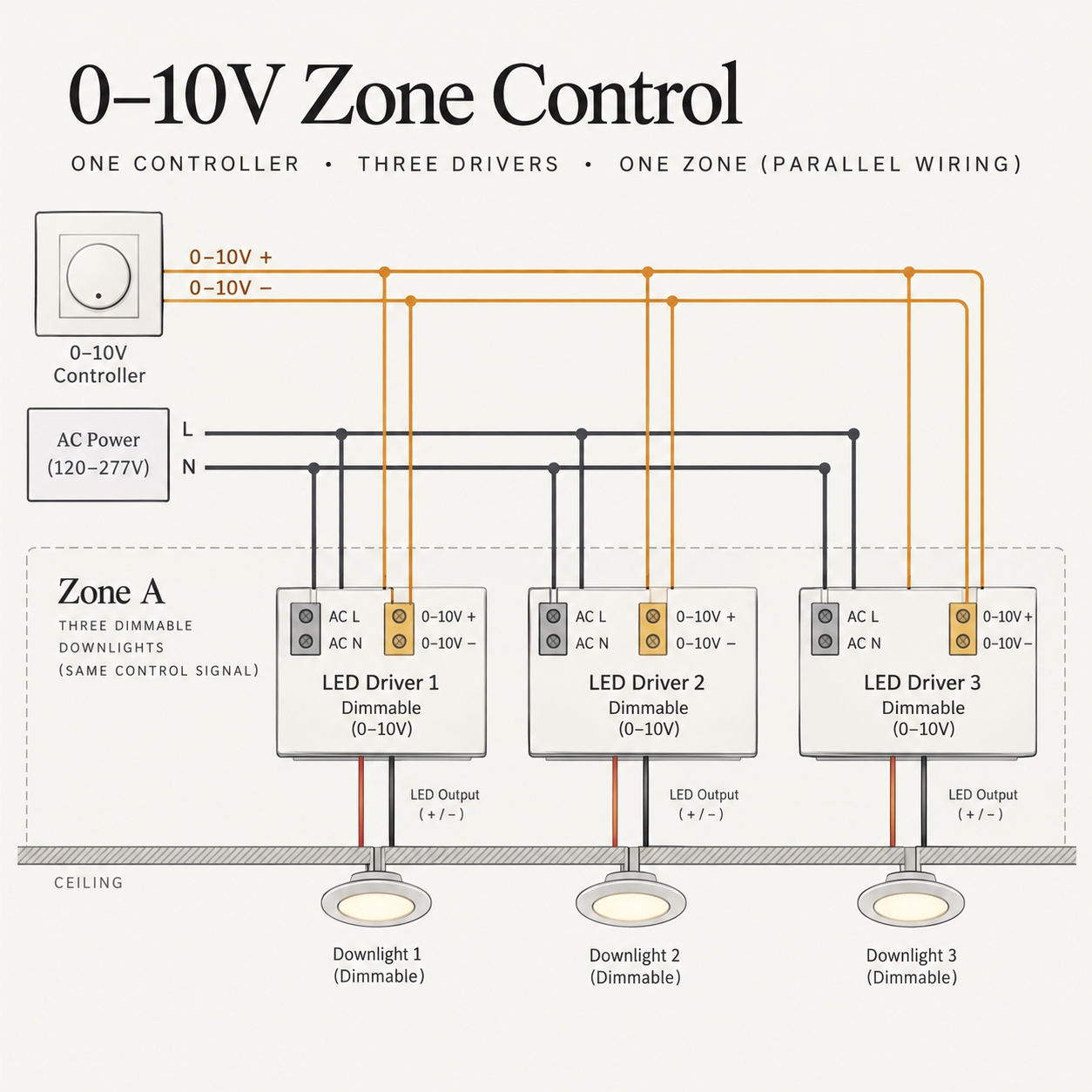
0–10V is an analogue control method. A control signal is sent to a compatible LED driver through a pair of control conductors, while the driver also receives its normal power supply. Changing the control signal requests a different light output.
It can be useful when several downlights are controlled together as one zone. However, “0–10V” on two product labels does not by itself guarantee identical behaviour. Confirm whether the control and driver use compatible current-sourcing and current-sinking arrangements, and check the control’s capacity for the number of connected drivers.
Also verify the response at the bottom of the range. Some combinations dim to a minimum level and require a separate switching device to turn fully off; others support dim-to-off. The relationship between control voltage and light output can vary between products, so test mixed-driver installations before ordering. A study of market-available 0–10V LED systems found substantial variation in output at a given control voltage.
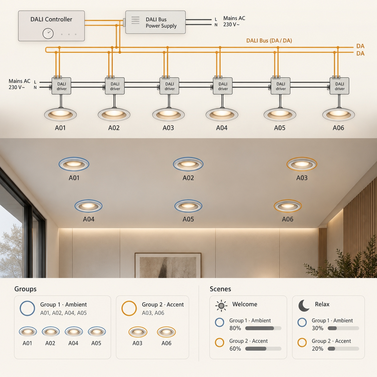
DALI stands for Digital Addressable Lighting Interface. It uses digital communication over a two-wire bus. Compatible devices can be configured into groups and scenes, and the system can exchange status information with supported equipment.
DALI can suit larger projects where different areas need separate schedules, scenes or flexible grouping. In a hotel, for example, it may support coordinated scenes across a lobby or restaurant. In an office, it may allow lighting zones to be adjusted as the space changes.
These features require system design and commissioning. Specify the driver and control-device capabilities, plan the bus and its power supply, and allow for addressing and scene setup. If DALI-2 certification is required, confirm it for the exact products rather than relying on a general “DALI compatible” description.
For a small renovation: first identify the installed dimmer and wiring. A compatible phase-cut driver may be practical if a tested combination meets the required dimming performance.
For several fixtures operating as one zone: 0–10V may be suitable when the control wiring and driver interface are planned together.
For a larger project with multiple scenes and separately controlled areas: DALI may provide the needed flexibility, provided the project includes commissioning and ongoing system support.
These are starting points. Project size alone does not determine the answer; the required functions, existing infrastructure and exact equipment matter more.
Request confirmation for the exact downlight and driver configuration being quoted. The specification should state:
Test a sample circuit across the full range, including low light levels. Check for visible flicker, sudden jumps in brightness, uneven behaviour between fixtures, audible noise and unreliable turn-on. Poor driver and dimmer pairing can produce flicker even when both components are individually described as dimmable.
Choose the dimming system at the same time as the downlight driver. Leading-edge and trailing-edge controls alter the AC supply waveform; 0–10V sends an analogue control signal; DALI uses addressable digital communication.
Whichever method you select, specify the exact driver and controller, confirm their compatibility and test the finished dimming behaviour. A successful system should feel smooth and predictable to the people using the space.
Building 2, No.442, Wuyi Road, Jianghai District, Jiangmen City, Guangdong, China.
admin@inbright-lighting.com
0086 - 13424998756
Copyright © Jiangmen Inbright Lighting Co., Ltd All Rights Reserved. 粤ICP备2025393167号 Sitemap XML